|
|
 |
| RO/RO RAMPS |
| |

The spectacular evolution of the Roll-on/Roll-off technique for shipping vehicles over the past few years has forced many ports throughout the world to provide suitable installations for this type of port traffic.
In ports with moderate tidal movement, the installation of a jointed type of ramp was deemed necessary. These freely absorb the oscillations in the deck level of moored boats.

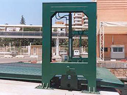
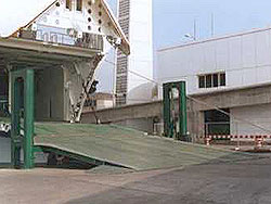
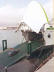
Generally, this type of installation consists of a metal gangway (with the requisite dimensions for each case) that is jointed on the ground. It is driven by a mechanism that allows it to reach a suitable contact position with the boat, and it can be supported directly by the boat or by the boat’s gangway.
|
| |
This system can have numerous driving systems: electro-mechanical; electro-hydraulic; or a combination of both.
 An endless number of additions can be adapted to this basic type, lending it a greater or lesser degree of perfection. These include automatic rabetting at different levels, automatic tidal following, shock absorbers, etc. An endless number of additions can be adapted to this basic type, lending it a greater or lesser degree of perfection. These include automatic rabetting at different levels, automatic tidal following, shock absorbers, etc.
The universal type developed by ITP is particularly suitable for ports with highly varied sea traffic with tidal movements of 3-4m.
Its basic dimensions are 6 to 12m wide and 12 to 20m long. In terms of its load capacity, this varies between 60MT and 100MT, which is more than sufficient for normal traffic nowadays.
Most installations designed by ITP S.L. work hydraulically. The ramp is located at the desired level through individual hydraulic cylinders located on either side and in the middle of the ramp’s body. These cylinders have been designed to be able to directly absorb the entire load when the ramp is in use. |
| |
| |
| Loads and overload |
| |
| When making calculations for the ramp, the following factors have been taken into account: the ramp’s own weight, the effect of a precise load at one end produced by the support of the boat’s gangway, and the overloads specified in current Spanish directives for road bridges. The sum of the resultant stresses on the most unfavourable load positions are increased by a co-efficient of 1.5. |
| |
| |
| |
| |
| Mechanism and control cabin |
| |

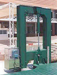
There is a mechanism and control cabin on one side of the columns. This comprises a structure with laminated sections that is covered by polished metal plates. There are glazed openings at the front and on the sides that allow perfect visibility of manoeuvres. There is a locking side-door and a wooden floor.
There is enough room for the electro-hydraulic mechanisms, the control and inspection desk, and there is also room for the operator.
|
| |
| |
| Safety |
| |
In this project, special attention has been given to guaranteeing the ramp’s continuous function; this is because of the considerable upheaval that would be caused by the ramp being out of order for a long period of time.
Thus, in order to absorb the blows incurred during regular service, the ramp has been fitted with robust hydraulic cylinders with ball joints, which allow abnormal movement in every direction.
On the other hand, the consequences of the eventual impact of the vessel’s incorrect movement are minimised through the ramp’s original joint system, which allows 0.5m movement without causing damage. If this is exceeded by a certain amount of stress, the easily-replaced safety bolts will break, thus avoiding damage to the installation.
|
| |
| |
| Level variations |
| |
| If desired, the ramp can automatically adapt to changes in the level of the tide through ultra-sound control, which is the equivalent of sonar. With this ingenious device, a high frequency transmitter directs sound waves at the water and receives the echo. This is instantly analysed and a message is sent to the mechanism that controls the ramp so that this, in turn, works. |
| |
| |
|
|

