|
| MARINE HOISTS (Pages 3 to 3) |
| |
|
| |
|
| Elevation Mechanism |
| |
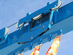
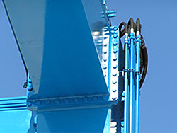
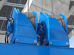 The elevation mechanism mainly consists of two hydraulic winches on each side that move the multi-fibre metal cables, which are guided by two grooved polymer pulleys that contain anti-friction pads instead of the steel pulleys that were previously used. These new pulleys do not require greasing. The elevation mechanism mainly consists of two hydraulic winches on each side that move the multi-fibre metal cables, which are guided by two grooved polymer pulleys that contain anti-friction pads instead of the steel pulleys that were previously used. These new pulleys do not require greasing.
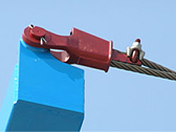
The cable anchors are Crosby – Lauchlin wedge anchors, which facilitate repairs to cables and their substitution. |
  |
| |
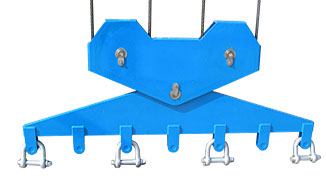
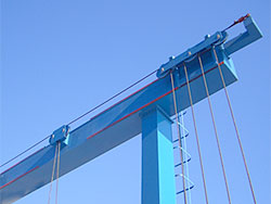
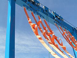
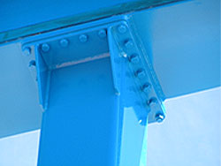
The cables pull on the girders to which the slings are attached. There are numerous attachment points for slings along the entire length of these load-bearing girders.
The polyester slings have been designed to comply with the new European Standard, and have a safety coefficient of 7 to 1.
There are also additional loops, safety couplings, load gauges and flexible eyes that are all large enough to support the vessel.
|
  |
| |
| |
|
| Hydraulic Equipment |
| |
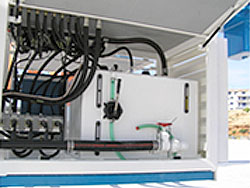 A diesel engine drives a variable movement pump to move the winches and the transmission. An auxiliary pump feeds the steering drums and the boom crane. It includes a hydraulic fluid tank with level and temperature gauges, as well as a filter that is checked visually. A diesel engine drives a variable movement pump to move the winches and the transmission. An auxiliary pump feeds the steering drums and the boom crane. It includes a hydraulic fluid tank with level and temperature gauges, as well as a filter that is checked visually.
The engine group has 4 soundproof access doors that are supported by gas cylinders.
Valves allow a range of gently progressive speeds for all marine elevation operations. The winch and transmission circuits have tested braking systems, and there are pressure-testing points at suitable places within the circuit.
|
|
| |
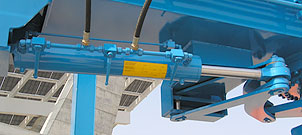
All cylinders have hard chrome plated piston rods with a nickel sub-layer to protect against corrosion and improve wear resistance.
All hydraulic elements are protected by safety valves on the service line, and there are also reserve relay valves to protect the entire circuit. |
| |
| |
|
| Working Controls |
| |
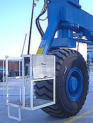
All the controls are located in the driver’s position, which can be found on the lower longitudinal section. It has safety rails and is accessed by steel steps. Alternative cabin positions can be supplied. The cabin allows the operator a 360o view.
If choosing a remote control system, the control pad covers all the machine’s elevation, steering and movement operations with proportional control pads that allow an infinite range of speeds. The control can be fitted on the control post’s dashboard. |
| |
|
| |
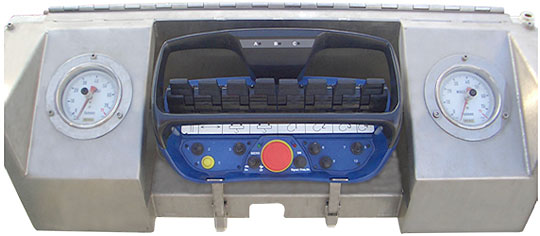
The control dashboard includes:
- Record of machine hours.
- Front and rear load gauges.
- Illuminated warnings for low oil pressure, overheating and battery charge.
- On/off ignition switch with key.
- Manually controlled accelerator.
- Tandem axle transmission for two-gear movement.
- Winch valves, steering valves and boom crane valves (if installed).
- Steering valves.
- Diagram of safe operating instructions for users. |
| |
 |
| |
| |
|
| Access |
| |
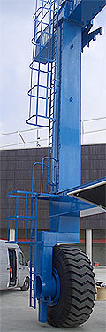 Equipment maintenance is an important, regular task that should be carried out on all cranes to keep them in perfect working order and prolong their working lives. Equipment maintenance is an important, regular task that should be carried out on all cranes to keep them in perfect working order and prolong their working lives.
Travel lifts have a set of vertical stairs with handrails and safety cages that allow technicians and operators access to the upper section of the machine where the cable pulleys, hydraulic pipes and cylinders for the longitudinal separation of slings are located.
The main electrical and hydraulic elements are on the lower part of the machine to allow easy access.
 |
| |
| |
|
| Surface protection and paint treatment |
| |
The pivots are made from 316 S 16 stainless steel. All steel components have been SA 2 ½ blasted and treated with high zinc phosphate content primer, and are painted with one base coat and two gloss coats of acid-resistant, quick drying epoxy.
All surfaces have at least three coats of paint with a thickness in excess of 200µ
Surface treatment
Initially, surfaces are shot blasted with steel until a rough surface of SA 2 ½ is achieved.
Then 3 coats of the following paint are applied:
- Enriched zinc phosphate-based primer, with a thickness of 60µ.
- 1st base coat, with a thickness of 100µ.
- 2nd double top coat, each 40µ thick. |
| |
| |
| |
| |
|