 |
| DOUBLE BOOM CRANES (Page 2 of 5) |
| |
|
| |
|
| Anchorage |
| |
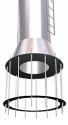
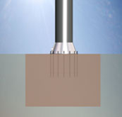
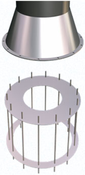 Like all other permanently fixed crane models, a special framework is supplied so that it can be erected in a solid piece of concrete in the middle of the intended launch area. Like all other permanently fixed crane models, a special framework is supplied so that it can be erected in a solid piece of concrete in the middle of the intended launch area.
The crane’s improved reach means it can be erected some distance from the edge of the quay, thus making the work of excavating for and installing the solid piece of concrete easier, safer and more economical.
  |
| |
| |
|
| Pivot and platform |
| |
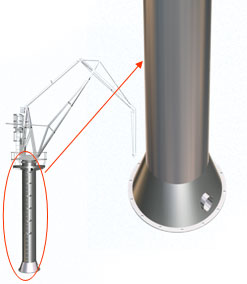
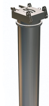 The fixed column comprises a circular tube. Its base is joined to and reinforced by a cone that is firmly fixed to the anchoring concrete.
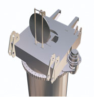
There is a rotating platform on top that supports the crane’s control turret and the principal turning, elevation and reach mechanisms.
The platform has a gangway that provides access to the five-ring electric slip-ring assembly.
 |
 |
| |
| |
|
| Control turret |
| |

The turret structure is joined to the rotating platform, and the crane’s main equipment and mechanisms are attached to it. |
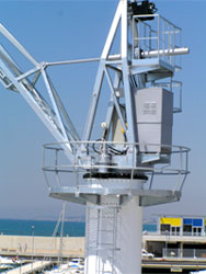
On one side there is a general electric box and the boxes for the transmission of the crane’s manual and remote controls.
On the back there are mountings to support the hydraulic group that supplies all the mechanisms for elevation, turning and range.
Halfway up there is a fastening for the boom range system’s hydraulic cylinder.
Finally, the winch for the elevation cable is fixed to the top. |
|
| Boom, brace and extension arm |
| |
| The crane’s retractable part consists of three independent, articulated structures that work together through sealed, chrome-plated, spherical swivelling joints. |
|
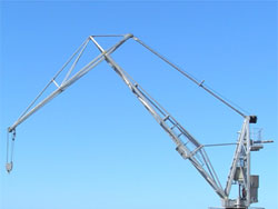
The articulated quadrilateral axes have been determined so that the end of the extension arm follows a virtually horizontal path as it moves from maximum to minimum reach, and vice versa. |
| |
| |
|
| |

